VGA Video in VHDL on FPGA
This project was carried out as part of learning VHDL. It is a VGA video signal generator, which allows displaying an image on a VGA screen. The project was carried out on a Terasic DE1 board (Altera Cyclone II FPGA). 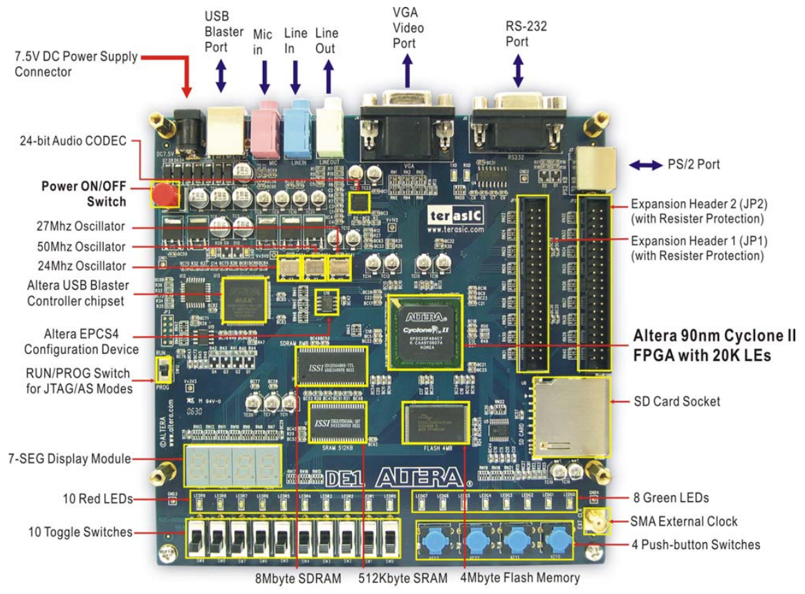
Objective
The goal of this project was to generate a VGA video signal, to display an image on a VGA screen. We therefore had to generate an HSYNC signal (horizontal synchronization), as well as a VSYNC signal (vertical synchronization), and an RGB signal (or at least one of these colors). The timing of these signals depends on the resolution, we chose a resolution of 640x480, which is the standard VGA resolution.
It is necessary to generate these signals at a precise frequency, to respect VGA standards. The refresh rate must be 60Hz, and the horizontal frequency must be 31.5kHz. It is therefore necessary to use counters to generate these signals.
We used Quartus II software in version 13.0sp1 to program the FPGA. The VHDL code was written using the text editor integrated into Quartus II.
RGB on the DE1
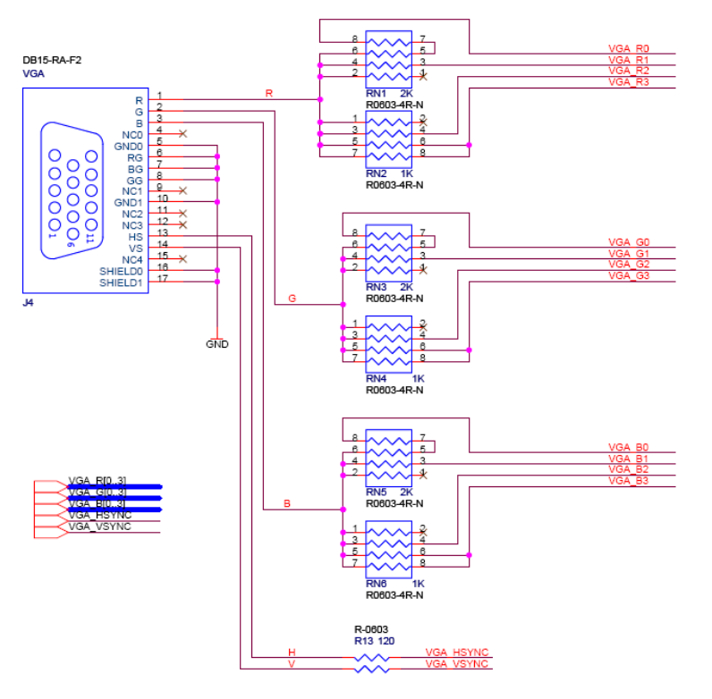
The RGB signal is generated using a DAC (Digital to Analog Converter). The DE1 board has a 4-bit DAC for each channel (Red, Green, Blue) which generates 16 different colors.
Block Diagram
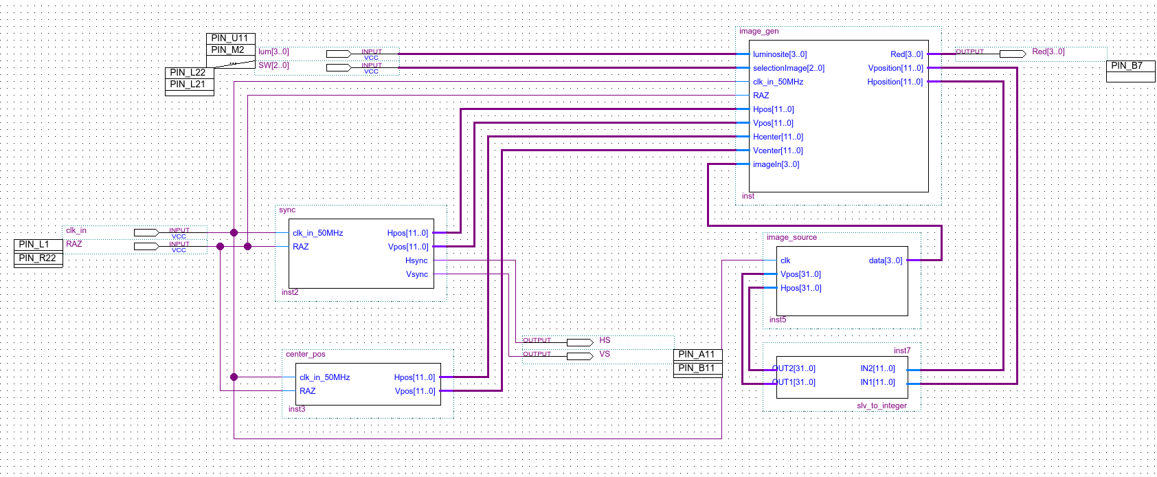
I created a block diagram to represent the project's operation.
 Click on the image to enlarge it
It consists of three main blocks:
- the
syncblock which generates synchronization signals - the
image_genblock which generates the image to display on the R/G/B pin - the
image_sourceblock which contains the image to display, a kind of hardcoded ROM
Synchronization Signal
The DE1 board having a clock signal at a frequency of 50MHz, it is necessary to divide this frequency to generate synchronization signals.
Horizontal Synchronization
Timing is very important in VGA. For horizontal synchronization, there must be a pulse lasting
We must therefore count up to 1589. This corresponds to a slv (for std_logic_vector, the equivalent of a std_logic array, bits) of 11 bits:
Pulse duration calculation:
We must therefore create a counter from 0 to 1589, with a logic output (std_logic) active during the first 189 values.
Vertical Synchronization
Vertical signaling is "based" on the H sync signal: the counter increases by one when the horizontal counter has finished a line (and therefore when it returns to 0).
The refresh rate being 60 Hz, this corresponds to a period of about 16.6 ms.
The output must be on during the first two lines, and the last two. We must therefore check if the counter is before 2 or after 521.
VHDL Code
VHDL code for synchronization signals
library IEEE;
use IEEE.STD_LOGIC_1164.ALL;
USE IEEE.STD_LOGIC_UNSIGNED.ALL;
use IEEE.numeric_std.all;

entity sync is
port (
   clk_in_50MHz, RAZ: in std_logic; -- clock input

	Hpos, Vpos: out std_logic_vector(11 downto 0);
	Hsync, Vsync: out std_logic -- output
  );
end sync;

architecture Behavioral of sync is
	-- internal counters
	signal Hcount: std_logic_vector(11 downto 0):=(others =>'0');
	signal Vcount: std_logic_vector(11 downto 0):=(others =>'0');

	-- Hsync constants
	constant HSYNC_DURATION: std_logic_vector(11 downto 0) := X"634";
	constant HSYNC_LOW_PULSE_END: std_logic_vector(11 downto 0) := X"0BC";

	-- Vsync constants
	constant VSYNC_DURATION: std_logic_vector(11 downto 0) := X"20A"; -- 522 -> 16.6/0.03177
	constant VSYNC_END_OF_STAR_PORCH: std_logic_vector(11 downto 0) := X"002";
	constant VSYNC_STAR_OF_END_PORCH: std_logic_vector(11 downto 0) := X"209";


begin
	 process(clk_in_50MHz)
	 begin
		 if(rising_edge(clk_in_50MHz)) then

			if(RAZ = '0') then
				Vcount <= x"000";
				Hcount <= x"000";
			end if;

			-- increment the internal counter by 1
			Hcount <= Hcount + x"01";

			if(Hcount = HSYNC_DURATION) then
				Hcount <= x"000"; -- counter reset

				Vcount <= Vcount + x"01";

				-- if we have reached the end of the 522 lines of the virtual screen
				if(Vcount = VSYNC_DURATION) then
					Vcount <= x"000";
					Vsync <= '1';
				else
					Vsync <= '0';
				end if;


			end if;

			-- between 0 and 188, i.e. 3.76us
			if(Hcount < HSYNC_LOW_PULSE_END) then
				Hsync <= '0';
			else
				Hsync <= '1';
			end if;

			if(Vcount >= VSYNC_END_OF_STAR_PORCH and VSYNC_STAR_OF_END_PORCH <= Vcount) then
				Vsync <= '0';
			else
				Vsync <= '1';
			end if;

		end if;
	 end process;

	 Hpos <= Hcount;
	 Vpos <= Vcount;
end Behavioral;Image Generation
The specifications for this block required being able to generate:
- a horizontal line (a few pixels wide)
- a vertical line
- a square
There is a small center_pos block that only serves to give the screen center to image_gen. It is then very simple to subtract or add a certain number of pixels to generate a horizontal or vertical line for example.
Four switches on the DE1 board allow you to choose the shape to display. It is possible to change shape by changing the switch values.
Horizontal and vertical lines
| Horizontal line | Vertical line | Square |
|---|---|---|
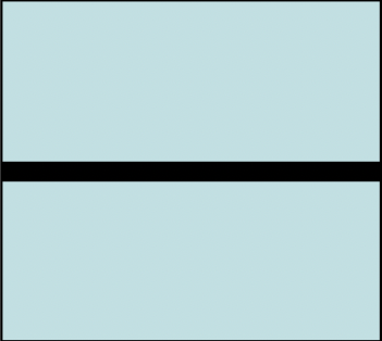 | 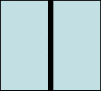 | 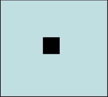 |
To generate a horizontal line, simply compare the current vertical position with the vertical position of the screen center. If the current vertical position is equal to the vertical position of the screen center, then display a pixel, otherwise display a black pixel.
if(Hp >= Hcenter-10 and Hp <= Hcenter+10) then
    Red <= x"F";
end if;Similarly, simply do the same with the horizontal position to get a vertical line.
if(Vp >= Vcenter-10 and Vp <= Vcenter+10) then
    Red <= x"F";
end if;And finally, the square is nothing more than the combination of these two combinations:
if((Vp >= Vcenter-10 and Vp <= Vcenter+10) and (Hp >= Hcenter-10 and Hp <= Hcenter+10)) then
    Red <= x"F";
end if;Arbitrary Image
Once this project was completed, I wanted to continue experimenting with VGA. I therefore added an image_source block, which is actually a read-only memory, which contains the pixel values to display, according to their coordinates (X, Y). It is possible to change the values of this ROM by modifying the VHDL code. To facilitate the modification of this ROM, I created a small Python script that generates the VHDL code from an image.
Python code to generate the VHDL code for the ROM
import cv2
import numpy as np

filePath = "image.jpg"

# Read the image
img = cv2.imread(filePath, 0)

# resize image
img = cv2.resize(img, (160, 120))

# convert to 4 bit grayscale
bits = 4
img = np.right_shift(img, bits)


image_height, image_width = img.shape

# in form type image is array (0 to (vertical_size-1), 0 to (horizontal_size-1)) of std_logic_vector(3 downto 0);
arrayStr = ""

arrayStr += f"constant vertical_size : integer := {image_height};\n"
arrayStr += f"constant horizontal_size : integer := {image_width};\n\n"

arrayStr += f"type image is array (0 to (vertical_size-1), 0 to (horizontal_size-1)) of std_logic_vector({bits-1} downto 0);\n"

arrayStr += "constant data : image := (\n"

# each line should be in form (x"7", x"8", x"9", x"A")
for i in range(image_height):
    arrayStr += "\t("
    for j in range(image_width):
        arrayStr += f"x\"{img[i][j]:X}\", "
    arrayStr = arrayStr[:-2]
    # if not last line, add comma
    if i != image_height - 1:
        arrayStr += "),\n"
    else:
        arrayStr += ")\n"

arrayStr += ");"

arrayStr += "\n -- image size: " + str(image_height) + "x" + str(image_width) + "\n -- bits: " + str(bits) + "\n -- image: " + filePath

print(arrayStr)It can be useful to extract a color from the image, I did it in an image editing software. Warning: the size of the image is important, if the image is too large, Quartus II will struggle and the FPGA will not be able to load it into memory.
Some image examples
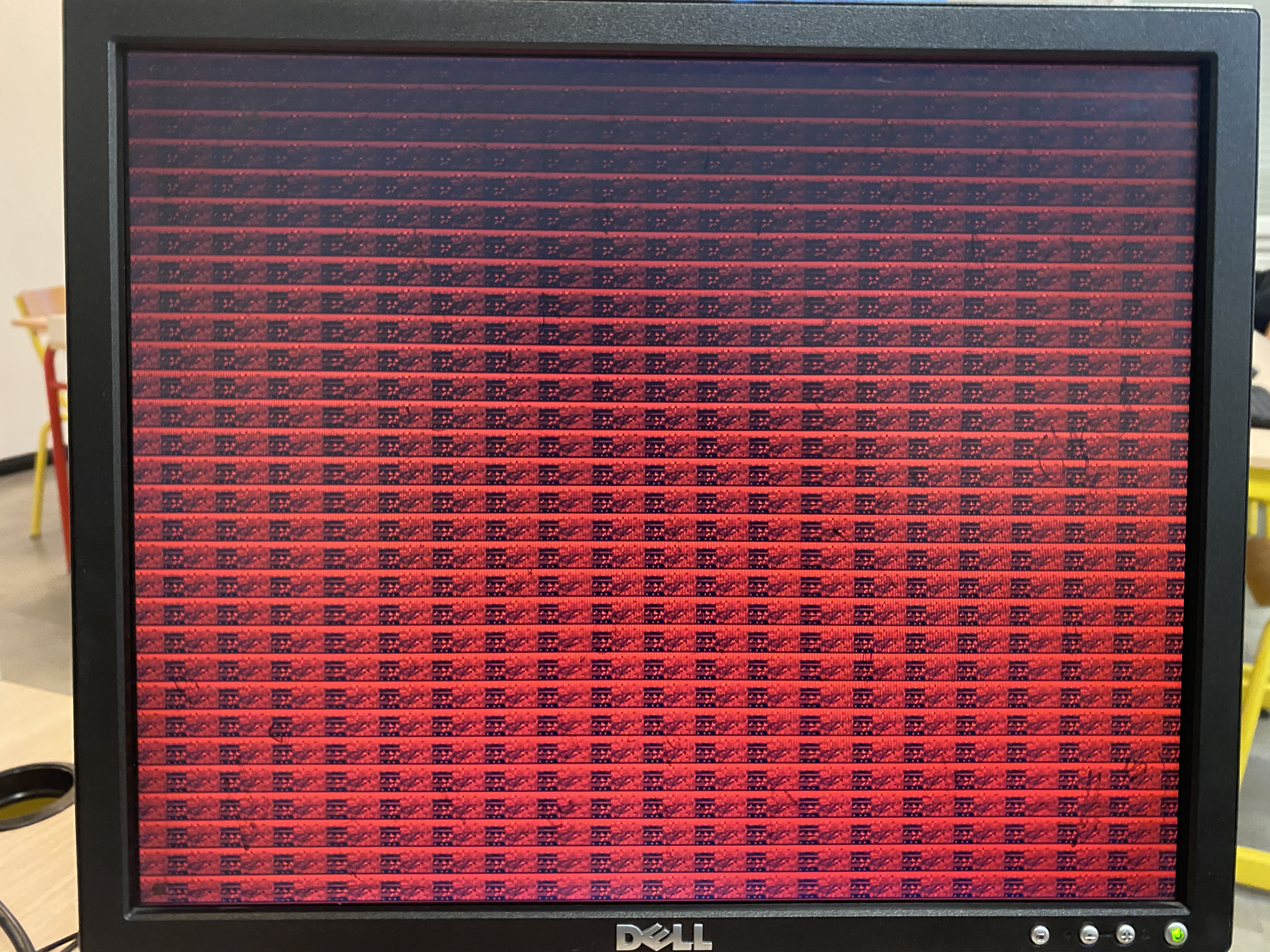
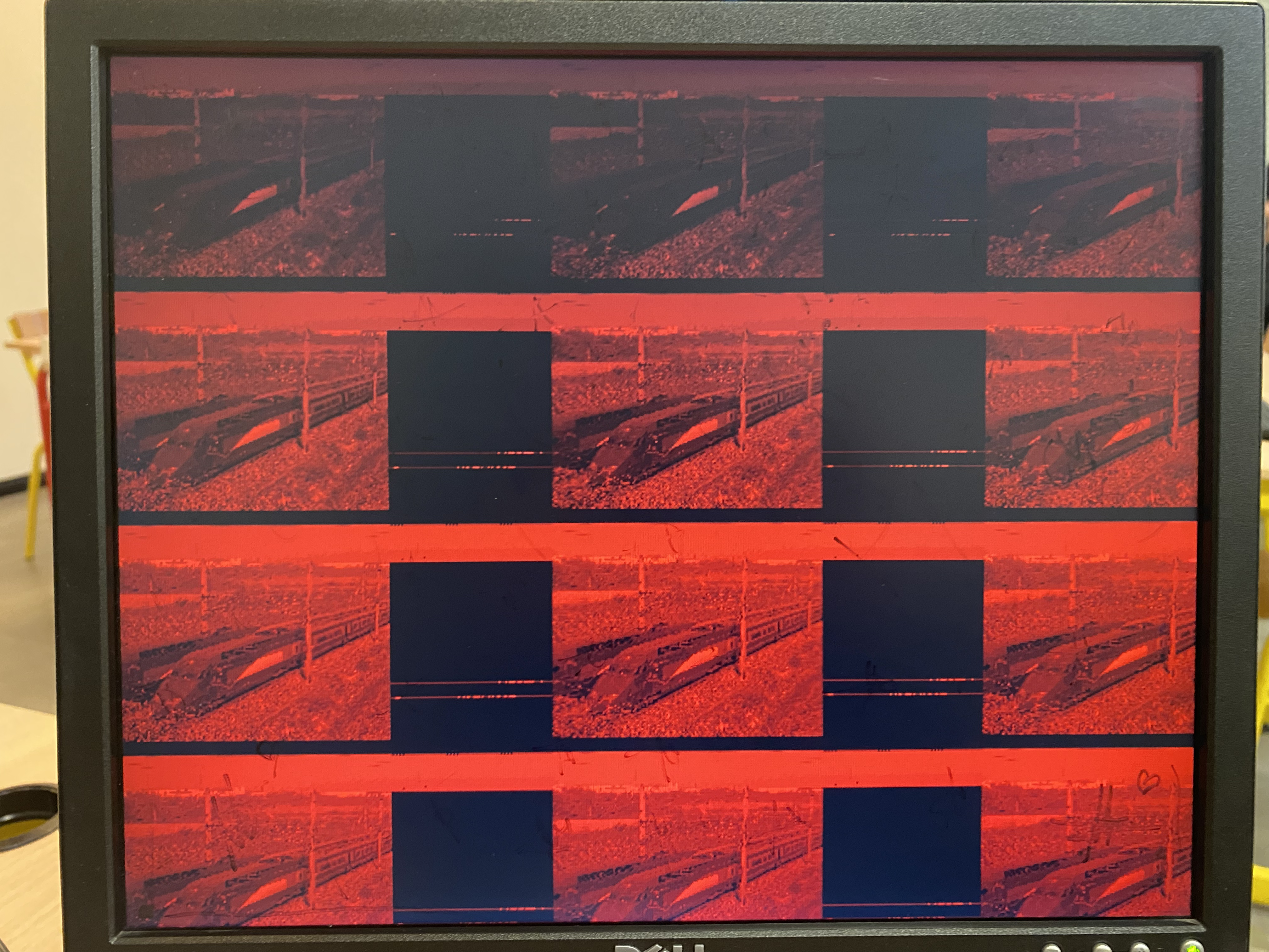
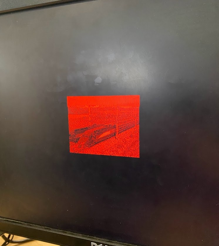
🎉 The first image is a 15x20 pixel image, the second is a 160x120 pixel image.
As you can see, the image is very red: I only connected one color out of the three. It is possible to connect all three colors, but then you must store the values of all three colors in the ROM, which takes up a lot of space.
The rendering is not perfect, but it is quite possible to recognize the image. It's a good start for a first VHDL project. 😄
To display the image, you must therefore read the ROM value at the current position (X, Y), and display it on the R/G/B pin. There is therefore a loop between image_gen and image_source. I patched together a slv_to_integer block for communication between the two blocks, to adapt the data types.
OUT1 <= to_integer(unsigned(IN1));
OUT2 <= to_integer(unsigned(IN2));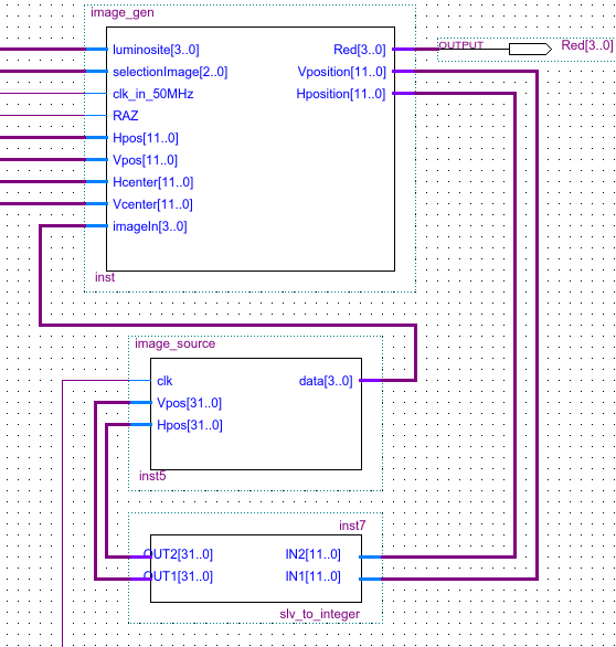
In the image_gen block, it is then enough to "let through" the ROM value at the current position (X, Y).
Red <= imageIn;Result
This project allowed me to learn many VHDL functions (although it remains relatively basic), and to understand how VGA works.
I would have liked to have more time to experiment with the SD card reader, to store the image directly on it and read it from the FPGA. Unfortunately, I didn't have time to do it. I also wanted to try to make a video move, but I didn't have time either.